 汉语
汉语
 English
 Français
 Deutsch


Direct Answer: The Turbo II™ Vapor Delivery System combines micro-droplet atomization with a highly efficient heat exchanger to deliver improved vaporization of liquid precursors for a wide range of applications. It provides a highly stable, low-maintenance solution for standard vapor delivery needs and enables the use of difficult liquid precursors by minimizing thermal decomposition, achieving vapor concentrations closer to theoretical limits, and providing the fast response times required for efficient short-pulse processing.
Table of Contents - Whitepaper
- What Are the Limitations of Traditional Liquid Vapor Delivery Solutions?
- How Does Heat Exposure Lead to Thermal Decomposition?
- How Does the Turbo II™ Vaporizer Atomizer Improve Efficiency?
- How Does the Turbo II™ Vaporizer Heat Exchanger Work?
- What Factors Optimize the Vaporization Process?
- How Does the Turbo II™ Provide Stable Concentration Output?
- How Fast is the System's Response Time?
- Is This a Field-Proven, Low-Maintenance Solution?
What Are the Limitations of Traditional Liquid Vapor Delivery Solutions?
Traditional liquid vaporizer solutions include vapor draw, bubblers, flash vaporizers, and direct liquid injection (DLI) valves.
A vapor draw solution uses a heated liquid ampule where temperature and volume determine the amount of vapor. The vapor is then introduced into the chamber with a fast-acting valve. While this method offers simple control and works for small concentrations of thermally stable liquids, it has drawbacks. Vapor concentration can vary with the liquid level, prolonged heating can cause thermal decomposition, and overall vapor concentration is limited.
A bubbler is similar but adds a carrier gas to increase vapor concentration and speed delivery. However, this method can create large liquid bubbles that escape and cause particle contamination downstream. With both vapor draw and bubblers, the liquid flow rate is not directly controlled, making it difficult to determine the precise vapor concentration.
A flash vaporizer or a DLI valve uses a push gas to move liquid through a liquid flow controller (LFC) for precise mass concentration control. The liquid passes through a heated throttling valve, forcing a pressure reduction that "flashes" it into vapor. While effective for low concentrations of thermally stable materials, achieving higher concentrations is difficult. These methods are also prone to clogging, incomplete vaporization, and thermal breakdown of sensitive materials, which can create solid particulate contamination.
The Turbo II liquid vapor delivery system overcomes these limitations by using a novel direct liquid injection and droplet atomization method. This vaporizer provides a wider process window, enabling the vaporization of thermally stable and sensitive materials at both high and low concentrations, including liquids with low vapor pressures.
How Does Heat Exposure Lead to Thermal Decomposition?
Using excess heat during vaporization can cause thermal decomposition. The rate of decomposition increases exponentially with temperature, as shown in equation (1). For example, TEMAZr (Tetrakis(ethylmethylamido) zirconium), a common precursor for ZrO₂ thin films, decomposes at approximately 1.4% per hour at 150°C and has a half-life of only 1.8 hours at 200°C. This highlights the need for a vaporization method that uses minimal heat and short exposure times.
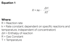
The primary method of vaporization is convective heat transfer to the liquid. The heat flow rate is directly proportional to the contact area and the temperature difference between the surface and the fluid, see equation (2).

Typically, a body of liquid is heated from the sides and bottom of its container. The Turbo II™ Vaporizer uses a more efficient droplet atomization direct liquid injection technique.
How Does the Turbo II™ Vaporizer Atomizer Improve Efficiency?
The Turbo II™ Vaporizer has two main components: the atomizer and the heat exchanger. The atomizer creates a fine spray of droplets from the liquid, which dramatically increases the surface area. As droplet diameter decreases, the total surface area of the liquid increases proportionally. This larger surface area leads to faster heat transfer, quicker vaporization, and reduced heat exposure time.
| Liquid Volume | Liquid Mass* mg | Droplet Diameter | Number of Droplets | Total Surface Area mm² | Total Specific SA mm²/mg |
|---|---|---|---|---|---|
| 0.524 | 0.524 | 1 mm | 1 | 3.14 | 6 |
| 0.524 | 0.524 | 1 µm | 109 | 3,141 | 6,000 |
| 0.524 | 0.524 | 500 nm | 8x10⁹ | 6,283 | 12,000 |
Droplet size distribution depends on the design of the liquid and carrier gas orifices, push pressures, flow rates, and the liquid's surface tension. The Turbo II vaporizer features a size-adjustable liquid orifice and a factory-adjustable carrier gas orifice, allowing it to be fine-tuned for specific liquid and carrier gas flow rates. This customization minimizes droplet size for each application. The nanometer-sized droplets generated enable extremely fast vaporization without preheating the liquid or carrier gas. A precision flow control Piezo valve on the atomizer further improves flow control, reduces dead volume, and suppresses liquid bubble formation.

Less exposure to heat lowers the risk of thermal decomposition. This efficient heating allows for faster and more complete vaporization at lower temperatures and higher liquid concentrations, closer to theoretical maximums. It enables the successful vaporization of liquids with a small window between vaporization and decomposition and makes it possible to generate high vapor concentrations, with rates greater than 6,000 g/hr achievable for high vapor pressure liquids.
How Does the Turbo II™ Vaporizer Heat Exchanger Work?
Located directly downstream of the atomizer, the Turbo II™ Vaporizer's heat exchanger is a heated zone designed with enough energy and residence time to fully vaporize the liquid at the desired concentration. This component is the result of focused research on optimizing heat transfer to micro-droplets.
Key design characteristics include:
- Multi-zone heating for effective heat control.
- Optimized temperature control point for faster heater response and minimal temperature differentials.
- Improved droplet transfer to maximize liquid surface area, speed up heat transfer, and reduce internal deposition and clogging.
- Minimized heat transfer path for faster evaporation and higher capacity.
- Maximized flow mixing to improve heat transfer to the liquid.
- Minimized internal volume for faster vapor response times.

Vaporization occurs as atomized droplets mix with the gas flow. Heat transfer happens indirectly through the gas to the suspended droplets, eliminating direct liquid-to-hot-surface contact. This design keeps internal surfaces clean, prevents clogging, and reduces maintenance. Droplet temperature remains low due to evaporative cooling, which greatly reduces or eliminates thermal decomposition.
The atomizer and the heat exchanger combine to form the Turbo II Vaporizer. Additionally, a mass flow controller is needed to control the carrier gas flow, a liquid flow controller is used to control the liquid flow, and a temperature controller is used to control the heat exchanger temperature. Argon and Nitrogen are the most frequently used carrier gases in Turbo II Vaporizers. The use of Helium as a carrier gas is not recommended due to expense and global shortages; however, it can be used if the process requires it. A temperature limit controller is typically used to provide flexibility in overtemperature protection; however a thermostat can also be used. A vapor filter can be used downstream of the vapor delivery system to provide risk mitigation for any particulates that could be in the line upstream of the vapor delivery to the chamber.

What Factors Optimize the Vaporization Process?
Saturation vapor pressure, enthalpy of vaporization, and molecular weight are important parameters to consider for optimizing vaporization. Saturation vapor pressure determines the maximum amount of liquid that can exist in a gaseous state at a given temperature. If it limits the desired precursor concentration, the carrier gas flow rate can be increased to reduce the system's vapor pressure.
Figure (4) shows saturation vapor pressures as a function of temperature for several different liquids commonly used in CVD/ALD applications:
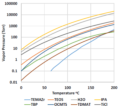
Low saturation vapor pressures also lead to low evaporation rates, making vaporization at high concentrations challenging. The Turbo II™ Vaporizer is well-suited for low vapor pressure precursors because it significantly increases the liquid's surface area and heat transfer efficiency.
The required heater power for complete vaporization can be calculated using the liquid's enthalpy of vaporization, the heat capacity and molecular weight of the liquid and carrier gas, and the operating temperature differential. This helps ensure the vaporizer provides enough energy to completely vaporize the desired liquid flow rates.
Table (2) details enthalpy of vaporization and molecular weight values for TEOS, IPA and H2O, showing the wide range of energy needed to vaporizer 1 gram of different liquids.
| Liquid | Enthalpy of Vaporization (kJ/mol) |
Molecular Weight (g/mol) |
Energy to vaporize 1 gram (J) |
|---|---|---|---|
| TEOS | 54.8 | 208.3 | 263 |
| IPA | 44 | 60.1 | 732 |
| Water | 40.62 | 18.02 | 2254 |
| OCMTS | 47.6 | 296.62 | 160 |
| TDMAT | 53.8 | 224.19 | 240 |
| TiCl | 39.8 | 189.679 | 210 |
| TBP | 61.4 | 266.32 | 231 |
| TEMAZr | 85 | 323.63 | 263 |
The Turbo I™ Vaporizer provides enough energy and residence time for a wide array of applications. Even and efficient heating of the liquid (a combination of increased liquid surface area and uniform heat distribution) leads to faster and more complete vaporization at lower temperature set points and higher liquid concentrations – closer to theoretical maximums.
How Does the Turbo II™ Provide Stable Concentration Output?
The Turbo II™ Vaporizer provides highly stable concentration output through several key design features:
- Direct Liquid Injection: The mass flow rate is metered by a high-precision liquid flow controller, like the 2950 Turbo™ LFC, providing stable mass flow rates and precise control. This prevents the concentration drift common in bubbler and ampule systems.
- Complete Vaporization: By ensuring 100% vaporization, the system avoids mass concentration drift and persistent clogging seen in other DLI systems, resulting in stable output with reduced maintenance.
- Liquid Bubble Suppression: The vaporizer is designed to suppress the formation of bubbles in the liquid line, which can cause vapor concentration and pressure variability.
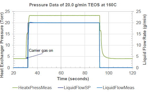
Figure (5) is an example of a liquid mass flow delivery stability and pressure stability immediately downstream of the Turbo II Vaporizer. Mass flow and downstream pressure typically stay within ±1% of set point. Depending on downstream configuration, chamber pressure variability will be 10 to 100x less than pressure fluctuation directly downstream of the vaporizer.
How Fast is the System's Response Time?
Response time is becoming more and more important for short-cycle applications like ALD and pulsed CVD. There are two key response times: the response time of the liquid flow controller (LFC) and the response time of the vapor output.
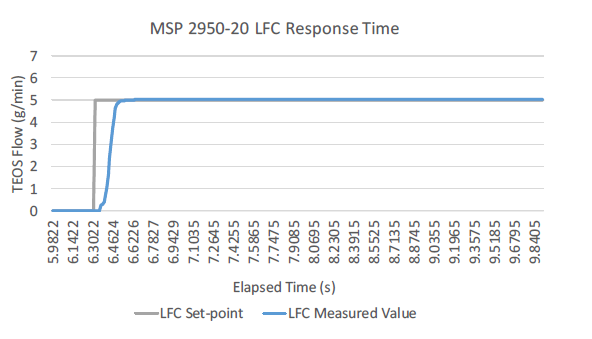
The LFC response time is a function of its sensor, electrical design, and control valve. The Turbo II's onboard Piezo valve and design prevent issues that can slow LFC response, such as threshold pressure requirements or valve sequencing problems. Figure 6 is an example of a liquid response time curve using a 2950 Turbo™ LFC and a Turbo II Vaporizer. For specification purposes, the liquid flow response time is defined as time to ±1% of Set Point. In this case, the LFC liquid response time is ~250ms.
Vapor response time depends on dead volume, pressure differential, carrier gas flow rate, and vaporizer design. The Turbo II vaporizers are engineered to almost completely eliminate dead volume. Vapor response time decreases with lower downstream pressures and higher carrier gas flows, reaching less than 0.1s at very low pressures (<10 Torr).
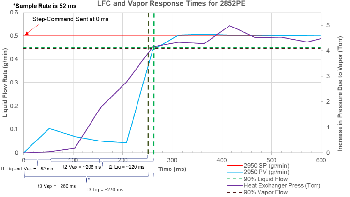
Figure (7) and table (3) detail the vapor response time of the Model 2852PE Turbo™ Vaporizer.
| Value | Liquid | Vapor |
|---|---|---|
| t1 (initial response after step-command) | 52 ms | 52 ms |
| t2 (time from initial response to 90% flow) | 208 ms | 220 ms |
| t3 (total time from step-command to 90% or 90% of pressure increase from vapor) | 260 ms | 270ms |
Is This a Field-Proven, Low-Maintenance Solution?
Yes. While newer than conventional techniques, the Turbo II™ vaporizer has been used extensively in 300mm fabs globally for over a decade. It is trusted in CVD and ALD tools for challenging processes involving low vapor pressure, highly thermolabile, or high-flow liquids. It is also widely chosen for simpler applications due to its highly stable concentration output and field-proven, low-maintenance, clog-resistant design. This reliability allows the CVD tool it is installed on to run for years without vapor delivery issues.
Ready to Optimize Your Vapor Delivery System?
Discover how the Turbo II vaporizer can advance your vapor delivery processes. With micro-droplet atomization and an optimized heat exchanger, this solution ensures reliable vaporization of even the most challenging liquid precursors. Benefit from stable, low-maintenance operation and minimize issues like thermal decomposition or clogging. Explore the full potential of the Turbo II™ Vapor Delivery System to achieve optimal performance and efficiency for your CVD/ALD applications.
For a comprehensive technical overview, including performance data and detailed application insights, download our full whitepaper. Discover how this advanced liquid source delivery technology can optimize your deposition processes and enhance your competitive edge.
Takeaways
- Advanced Vaporization Technology: The MSP Turbo II™ Vaporizer uses innovative micro-droplet atomization and a highly efficient heat exchanger to overcome traditional vapor delivery challenges.
- Optimized for CVD/ALD Applications: It handles a wide range of liquid precursors, including those with low vapor pressure or narrow thermal windows, ensuring precise and efficient vaporization.
- Minimized Thermal Decomposition: By reducing heat exposure and optimizing heat transfer, the system prevents thermal decomposition, even for sensitive materials like TEMAZr.
- Stable and Reliable Output: The Turbo II™ Vaporizer ensures consistent vapor concentration and suppresses issues like liquid bubble formation, making it a low-maintenance solution.
- Fast Response Times: Designed for short-pulse processes like ALD, the system offers rapid response times with minimal dead volume and efficient flow control.
- Field-Proven Performance: Trusted globally in 300mm fabs, the Turbo II™ Vaporizer is a reliable, clog-resistant solution for both challenging and standard vapor delivery needs.
References
[1] B. Deal, A. Grove (1965), “General Relationship for the Thermal Oxidation of Silicon,” Journal of Applied Physics, 36(12), 3770-3778.[2] FMC Lithium Tetrakis(ethylmethylamido)zirocnimium (TEMAZ) product specification. URL https://1pdf.net/tetrakisethylmethylamidozirconium-temaz-_58ee1a64f6065dc851d1b21d
[3] D. Shenai, H. Li, Q. Wang, Y. Senzaki, R. Gordon, (2007). “Designing Suitable ALD Precursors for High-k Dielectrics, Barriers and Metal Applications”, AVS/ALD Conference, San Diego, 2007.
[4] B. Liu and Y. Ma, “Model 2800 Turbo VaporizerTM for TemaZ Vaporization”. Unpublished manuscript.
[5] B. Liu, T. Dinh, Y. Ma, (2015) US Patent Application US20130292485A1, “Fine droplet atomizer for liquid precursor vaporization”.
[6] B. Liu, (2013). US Patent US8132793, “Method and apparatus for liquid precursor atomization”.
[7] J. Sun, B. Liu, (2004). US Patent US6805907, “Method and apparatus for vapor generation and film deposition”.
[8] P. Obrien, N. Pickett, D. Otway, (2002). “Developments in CVD Delivery Systems: A Chemist’s Perspective on the Chemical and Physical Interactions Between Precursors”, Chem. Vap. Deposition 8(6), 237 – 249.
[9] D. Haussmann, E. Kim, J. Becker, R. Gordon, (2002) “Atomic Layer Deposition of Hafnium and Zirconium Oxides Using Metal Amide Precursors,” Chem. Mater, 4350 – 4358.
[10] J. Chickos, W. Acree, (2002), “Enthalpies of Vaporization of Organic and Organometallic Compounds, 1880–2002, J. Phys. Chem, 32(2), 519-878.
[11] C.M. Invernizzi, P. Iiora, D. Bonalumi, E. Macchi, R. Roberto, M. Caldera, (2016), “Titanium tetrachloride as novel working fluid for high temperature Rankine Cycles: Thermodynamic analysis and experimental assessment of the thermal stability,” Applied Thermal Engineering, 107, 21-27.
[12] N.K. Oh, J. Kim, J. Ahn, G. Kang, S. Kim, J. Yun (2016), 201CThe Effects of Thermal Decomposition of Tetrakis-ethylmethylaminohafnium (TEMAHf) Precursors on HfO2 Film Growth using Atomic Layer Deposition,” Appl. Sci. Converg. Technol, 25(3), 56-60.
[13] A. Love, S. Middleman, A. Hochberg, “The Dynamics of Bubblers as Vapor Delivery Systems,” Journal of Crystal Growth, 129, 119-133.